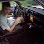
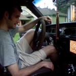
And now, ladies and gentlemen, the next exciting installment in the Carputer series!
MPM: NEVER BEFORE IN THE HISTORY OF CAR ACCESSORIES HAVE SO MANY SMALL ELECTRONIC GIZMOS COMBINED TO MAKE A SINGLE GIZMO SO FRIGGIN’ SWEET…
Yes, yes. Anyway, I would like to –
MPM: AN ORDINARY CAR…
Ahem. What?
MPM: AN EXTRAORDINARY JOURNEY…
Yes, but wait, what? This is just about the carputer itself, the trip is discussed elsewh-
MPM: AND ONE MAN’S VISION TO UNITE THEM ALL…
Okay, just keep going. I think this time you actually won’t stop until you get to the-
MPM: THIS SUMMER…
Zach: I think it’s finally ready.
Zach’s Mom (V.O.): Now you take it easy out there, son. You’ve been working on that thing all day.
Zach: I’m so close I can… I can taste it.
MPM: ZACH BARDON…
Zach: Okay, let’s do this. (deep breath)
(sound of engine starting)
Zach’s Dad: (approaching) You got it working?
MPM: AND THE LOVEMOBILE, IN…
Car (V.O.): Welcome, Zach.
MPM:
CARPUTER 3: THE INSTALLATION
(sound of car driving away)
Car (V.O.): Turn… left… in… 500… feet.
Actually, that was pretty cool how you talked all big like that. Although if a person installing electronics in his car is movie material, we are an entertainment-starved culture, to be sure.
For those of you just joining us, I have previously described how I realized a carputer would be friggin’ sweet, so I built one, then put all the awesome software on it that I wanted. I will now describe Step 3 in the carputer process – getting all the aforementioned pieces in the car and connected so they work.
The Master Plan
The plan in a nutshell: fused power wire running on right side from battery to trunk. Mainboard with power supply under passenger seat, touchscreen in dash (powered from power supply, not battery), foldable keyboard stowed under the seats when not in use. GPS receiver on back deck. Wi-fi antenna mounted on hood in place of previous radio antenna. Audio running down left side from carputer to trunk. Accessory wire run from previous stereo’s connector to power supply to serve as power switch.
The plan outside of the nutshell looks like this:
Exciting eh? Turns out the insides of nutshells are boring and leave out a lot of words, like articles and linking verbs. Let me give you more juicy details from outside the nut.
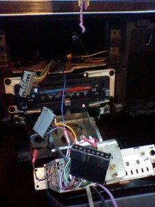
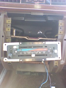
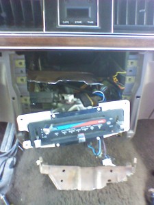
First, the touchscreen. As I said, my plan was to remove the existing head unit,
move the climate controls down lower,
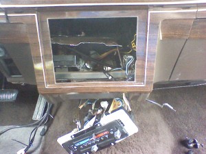
then cut out the plastic divider between them,
in order to use the entire space for the touchscreen. As it turned out, my plan could not have been more awesome.
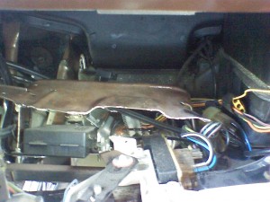
Midway through the above, I held up the touchscreen to the slot and discovered that there was also a metal divider inside separating the two DIN slots (see above) that had to go. It was too integrated into everything else to remove, so I just Dremeled off the front inch or two.
PRO TIP: cutting metal in a very confined area surrounded by other parts, including fairly important stock wire bundles is not the simple task that being able to write about it casually in one sentence might make it seem. To be. Yeah, it was more like that sentence – difficult.
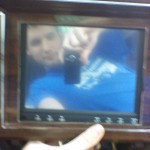
After that, there was enough space for the touchscreen!
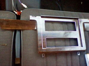
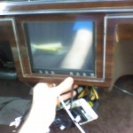
The next thing to think about was how to attach said touchscreen. For help in brainstorming, I held the screen in place and held the trim piece over it.
And – it looked great. It was the perfect size for that space; when I screwed the trim piece back on the screen was held securely in place by just pressure and friction! No crazy jerry-rigging necessary.
“That’s awesome!” exclaims Attractive Girl, ever supportive of that which is awesome.
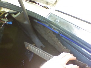
Next step: THE POWER. I mentioned how I had purchased an 8-gauge Kicker wiring pack, which made this step fairly simple. I simply ran the cable from the engine compartment back to the trunk, following the car’s existing wiring channel. The trickiest part was finding a way through the firewall, but I was able to locate a little rubber bushing about the right size that was unused in my no-power-options Vic, and pushed it through that. Again, that was one sentence, but it required the help of another person and took quite a few minutes and exploratory feeling and prodding. From there, it was a simple matter of unscrewing the “running boards” and prying up some carpet and plastic trim to expose the wiring channel, then running the cable down that into the trunk, where I cut off the excess wire.
I did need to spend a little time adding in a T connector near the passenger seat, where I would be running a smaller power line over to the carputer. I waited until I had installed the power cord almost exactly where it was going to be, before pulling a little slack in the cord, cutting a little hole in the under-seat carpet, and running the cord under the carpet over to that hole. Only then did I cut the power wire and splice in that T connector.
“Right, so you’ve got power going under your seat and to the trunk, and you’ve got a completely unconnected touchscreen sitting nicely in your dash. When do we get to the juicy stuff we saw in the preview?”
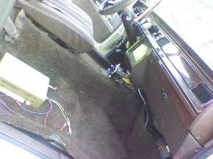
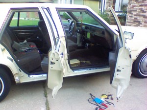
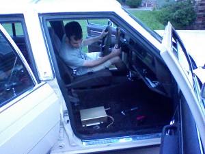
Trust me, I felt the same way. Next, it was time to get down to business and connect all of the many things that needed to be connected to the carputer itself. So I took out the passenger seat, and attached the carputer to the carpet, using the case’s handy peg-mounting system. (Pro tip: don’t try to drill holes in carpet, you’ll make a mess. Just slash little holes in it with a knife.)
Now I had nine wiring tasks ahead of me:
The Nine Wiring Tasks
- Power to the Opus power supply. A cinch: just had to run a few wires from the T connector to the Opus’s power wires.
- Grounding the carputer. Also fairly easy, since the seat bolted directly to the frame. I could just stick the ground wire from the Opus under the washer before tightening the bolt for a very solid, direct ground.
- Connecting the Opus’s power-on line to the car’s accessory power for automatic power-on and -off with ignition. This is one of the very cool things about the Opus. Since I was no longer using the previous head unit connector, I simply located the accessory wire in that using a voltmeter and ran a wire from there.
- Power from the Opus to the touchscreen. The Opus system came with additional power out for the screen, which is excellent because it means the screen will turn on and off with the carputer. It also means the screen is protected from under-/overvoltage like the rest of the carputer, which it would not be if I wired power to it separately. To do this, I had to remove the wallwort-style plug from the monitor to expose the wires, then connect the power out lines from the Opus to that. It was a little tricky because the wires from the screen were quite small. I just guessed which was hot/ground based on color, but it works so I guess either I was right or it didn’t matter. A circuit is a circuit no matter which way the current goes, I suppose.
- VGA from the carputer to the touchscreen. I can’t recall at the moment, but I think I didn’t even need a VGA extension cable for this. I ran both this and the touchscreen’s power wires together under the carpet, popping up through a small hole directly in front of the carputer.
- External antenna from the wi-fi card to the hood. I had one of those handy-dandy magnetic antennas specifically designed for sticking on cars, and fortunately the cable was long enough, so I was able to run it under the carpet (trying to keep it away from the power line as much as possible), through the unused bushing for wires I didn’t have going to the passenger door, then up and out through the gap between the windshield and the hood. It’s not as nice as a directly replacing the previous radio antenna, but it’s still pretty nice and the 1” of wire that shows is quite inconspicuous.
- GPS receiver from carputer USB to the back deck. I mentioned earlier that this is one of the last things I did (other than audio). Until I bought a USB extension, it was sitting on my dash with unsightly wires dangling around. But I finally got the extension, and then I could run the wire down the right side and behind the back seat, finally popping out in the center of the back deck, where the GPS could happily sit and cook on hot days.
- RCA audio from the Opus’s RCA outs back to the trunk, where it would eventually connect to the amp. I would have loved it if the Opus had SPDIF out, but alas, only RCA (and a bit noisy at that… I discovered after installing the audio system that the mobo’s onboard audio is not super clean).
- Remote-on
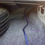 switch from the Opus to the trunk, to connect to the future amp. Another super awesome feature about the Opus is that it has a remote-on line, like head units which are designed to work with amps have. This line simply sends a signal to the amp telling it to turn on or off, which is a good idea because a) you don’t need to run switched power to the amp, which would be a pain, and b) the head unit turns on the amp after it is already powered on, thus avoiding the loud POP that could otherwise happen. The Opus has this capability, like a good head unit, so I was happy to take advantage of it.
Tools You Need To Do the Same
- Screwdrivers/wrenches/sockets of whatever kind you need to take apart your car.
- Wire cutters/crimpers
- Voltmeter
- Flashlight
- Dremel Mototool, including wheels for cutting metal (you’ll use up at least one of those wheels).
- Utility knife (for trimming 8-gauge wires and cutting carpet)
- Wire fasteners (I recommend picking up a kit of various gauge connectors)
- As I recall, I made use of a clamp and needle-nose pliers as well, but I don’t know that those are strictly necessary.
Sound like a lot of wiring? That’s because it was, and it definitely didn’t all get done in one day. All wires were run neatly down existing channels or under the carpet, tucked and fastened in various places so as to minimize risk of both chafing and signal interference.
Then, almost as an afterthought, I connected the keyboard.
Denouement
Finally, everything was connected, exactly as in my plan. I was ready to throw the switch and see if it worked the same in my car as it had on my dining room table.
And you know the rest because the preview kind of gave it away. Great job Movie Preview Man.
MPM: THEY KNEW TOO MUCH…
Yeah.
Anyway,
Friggin’ sweet! You have no idea how satisfying it is to start your car, hear it say “Welcome, Zach,” and then watch it acquire a lock on 8 different satellites.
“What about audio?” complain some nearby teenagers, completely expectedly.
Never you fret, my good teenagers. Do you think that I, a musician, could possibly design a car system that did not include audio as a primary consideration? Impossible! Well, possible… but immensely improbable. The fourth and final article in the Carputer series will describe the installation of the audio, possibly in some kind of cinematic fashion. Oh, and I forgot to mention that the main villain in this particular post, who swore vengeance on the carputer in a very prophetic manner, died – but kind of vaguely. Like, he could have actually lived, possibly even gaining some additional powers or something. Yeah.

